neuer Blog
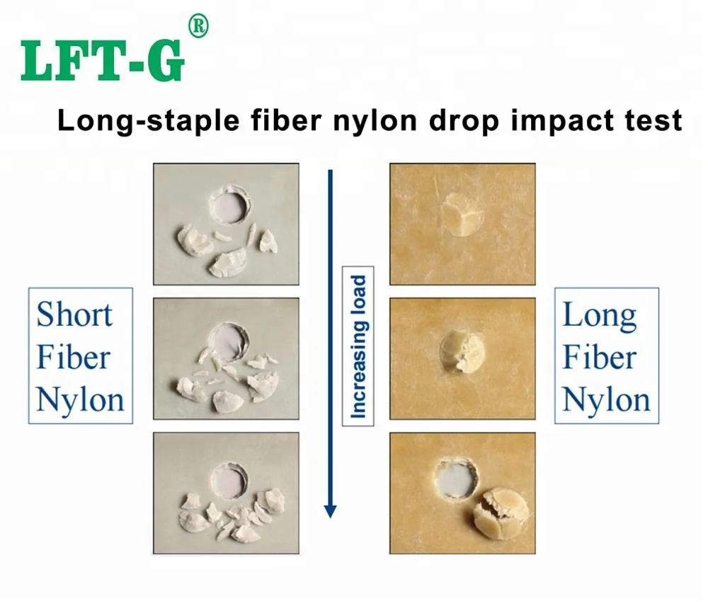
Dieselbe PA66-Rezeptur, dieselbe herkömmliche Kurzglasfaserbeladung – aber die Zugfestigkeit des spritzgegossenen Teils beträgt nur die Hälfte derjenigen des pressgeformten Teils.
Der Materialingenieur war ratlos: Wenn die Rohstoffe und der Fasergehalt exakt gleich sind, warum gibt es dann einen so großen Unterschied in der Leistungsfähigkeit?
Die Antwort liegt in nur zwei Worten:Faserlänge.
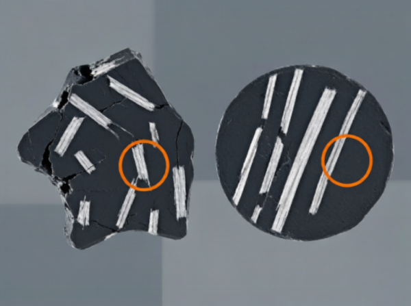
Beim Spritzgießen können die hohen Scherkräfte im Inneren der Schnecke Glasfasern auf eine durchschnittliche Länge von nur wenigen Millimetern zerbrechen.200–400 μmIm Gegensatz dazu ermöglicht das schonendere Kompressionsformverfahren, dass die Glasfasern ihre Länge beibehalten.2–4 mm oder sogar längerDie
Die Verstärkungswirkung von Glasfasern hängt grundlegend von derFaser-Seitenverhältnis (L/D)Je länger die Faser und je höher das Aspektverhältnis, desto effizienter kann die Spannung zwischen der Harzmatrix und den Fasern übertragen werden – was letztendlich die Festigkeitsgrenze des Verbundwerkstoffs erhöht.
Das Verarbeitungsverfahren schneidet die Fasern.Die Faserlänge bestimmt die maximale Leistungsfähigkeit.
1965 schlugen Kelly und Tyson das Einzelfaser-Auszugsmodell vor, das seither zu einer der theoretischen Grundlagen faserverstärkter Verbundwerkstoffe geworden ist. Seine Kerngleichung ist bemerkenswert einfach:
Woσcist die Festigkeit des Verbundwerkstoffs,σmist die Stärke der Matrix,Vfist der Faservolumenanteil,σfist die Faserfestigkeit.
Misst den Einfluss der Faserlänge auf die Spannungsübertragung. WennL > Lc, η nähert sich 1. WennL , η nimmt stark ab.
Misst den Einfluss der Faserorientierung. Bei perfekt ausgerichteten Fasern ist η₀ = 1; bei zufälliger Verteilung in der Ebene ist η₀ = 0,375; und bei dreidimensionaler Zufallsverteilung ist η₀ = 0,2.
Die Scherspannung an der Faser-Matrix-Grenzfläche muss über eine ausreichend lange eingebettete Faserlänge wirken, um die Last effektiv von der Matrix auf die Faser zu übertragen.
WoDist der Faserdurchmesser undτist die Grenzflächenscherfestigkeit.
Beispiel für glasfaserverstärktes PA66
σf ≈ 3400 MPa | d ≈ 13 μm | τ ≈ 30 MPa
Lc ≈ 740 μm
Im Kelly-Tyson-Modellτbestimmt die kritische FaserlängeLcJe höher die Grenzflächenscherfestigkeit, desto kürzer die kritische Faserlänge, wodurch kürzere Fasern Lasten effektiver tragen können.
Bei glasfaserverstärktem PP beispielsweise wird folgender Ansatz verfolgt:PP-g-MAHkann die Grenzflächenhaftung deutlich verbessern und die kritische Faserlänge reduzieren.
Viele Apotheker konzentrieren sich hauptsächlich aufGlasfasergehalt (Gew.-%)während man überblicktFaserlängeDies ist eines der größten Missverständnisse im Bereich faserverstärkter Kunststoffe.
Der grundlegende Unterschied zwischenLangglasfaser (LGF)UndKurzglasfaser (SGF)Es geht daher nicht nur um den Fasergehalt, sondern auch um die Fähigkeit, nach der Verarbeitung ein ausreichend hohes Faser-Aspektverhältnis beizubehalten.
| Komponente | Dosierung | Funktion |
|---|---|---|
| PA66 | Hauptkomponente | Matrix |
| Kurzglasfaser | Sekundärkomponente | Verstärkung |
| PA-kompatible Glasfaserdimensionierung | Wie erforderlich | Grenzflächenmodifikation |
| Matrix | Empfohlenes Kupplungssystem | Mechanismus |
|---|---|---|
| PP / PE | PP-g-MAH | Verbessert die Grenzflächenhaftung zwischen der Polyolefinmatrix und der Glasfaser |
| PA / PET | Matrixkompatible Glasfaserdimensionierung | Verbessert die Faser-Matrix-Haftung |
| Epoxidharz | Epoxysilan | Fördert die chemische Wechselwirkung mit der Epoxidmatrix |
Überprüfen Sie dietatsächliche FaserlängeDie SEM-Analyse der Bruchfläche kann übermäßigen Faserbruch aufdecken.
Glasfaserdurchmesser, Oberflächenbehandlung, Schneckendrehzahl und Verarbeitungstemperatur prüfen.
Eine übermäßige Faserbelastung kann verursachenschlechte Dispersion und Agglomerationwodurch Stresskonzentrationspunkte entstehen.
Mehr Fasern bedeuten nicht automatisch eine höhere Leistung.
Das eigentliche Ziel besteht darin, eine ausreichende Faserlänge zu erhalten und eine starke Faser-Matrix-Grenzfläche aufzubauen, damit die Fasern die Last effektiv tragen können.
Von PP-LGF und PA66-LGF bis hin zu Hochleistungs-LCF-Lösungen – unser technisches Team hilft Ihnen bei der Auswahl der richtigen Faserlänge, des richtigen Fasergehalts und der richtigen Polymermatrix für Ihre Anwendung.
Besprechen Sie Ihre MaterialanforderungenFolge uns :


-- Updates mit den neuesten Themen erhalten

 Email
Email Deutsch
 English
 français
 русский
 italiano
 español
 português
 العربية
 日本語
日本語 한국의
한국의 中文
中文